Kerf
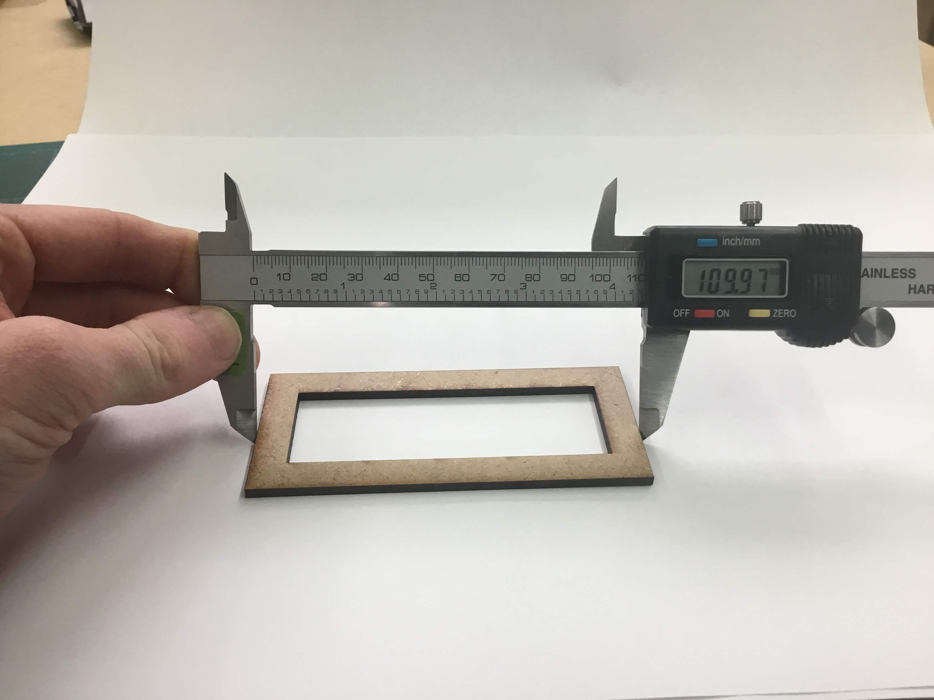
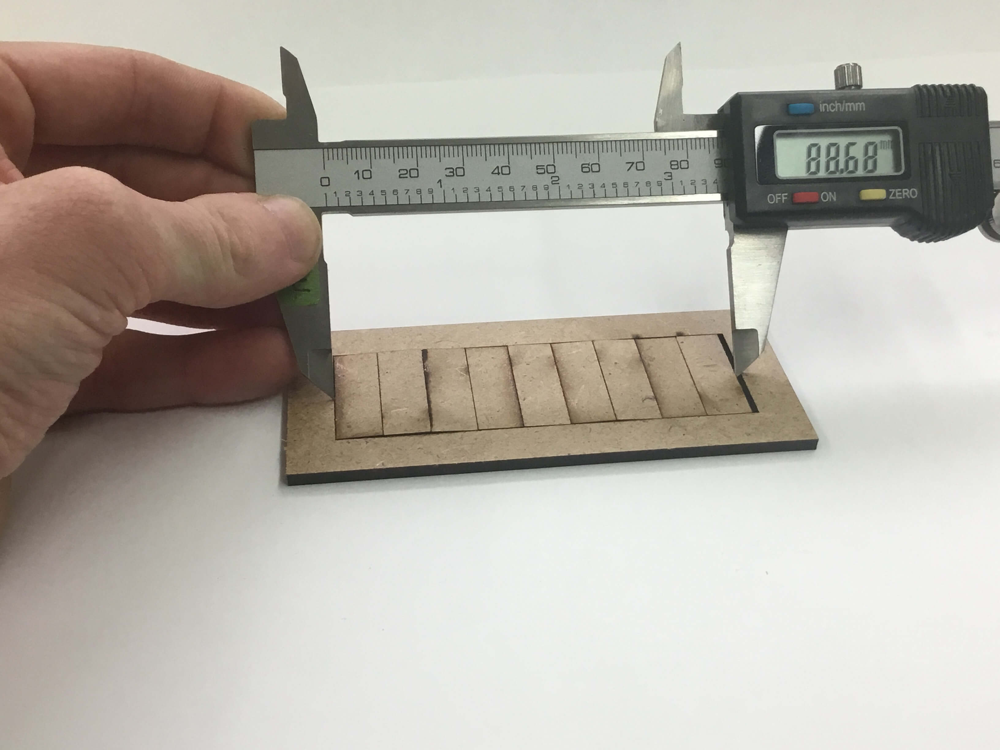
Michael made a Kerf measuring device:
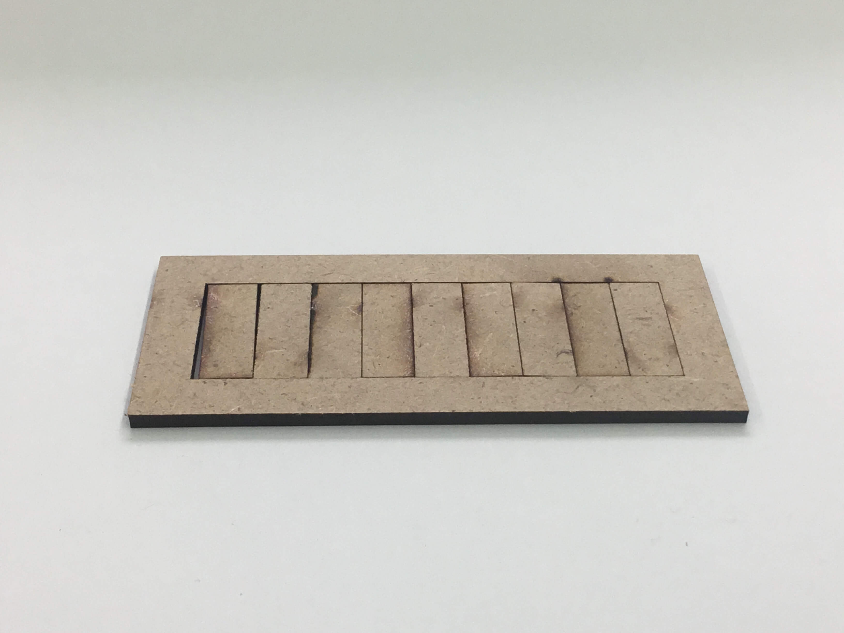
and a comb device for testing kerf slots
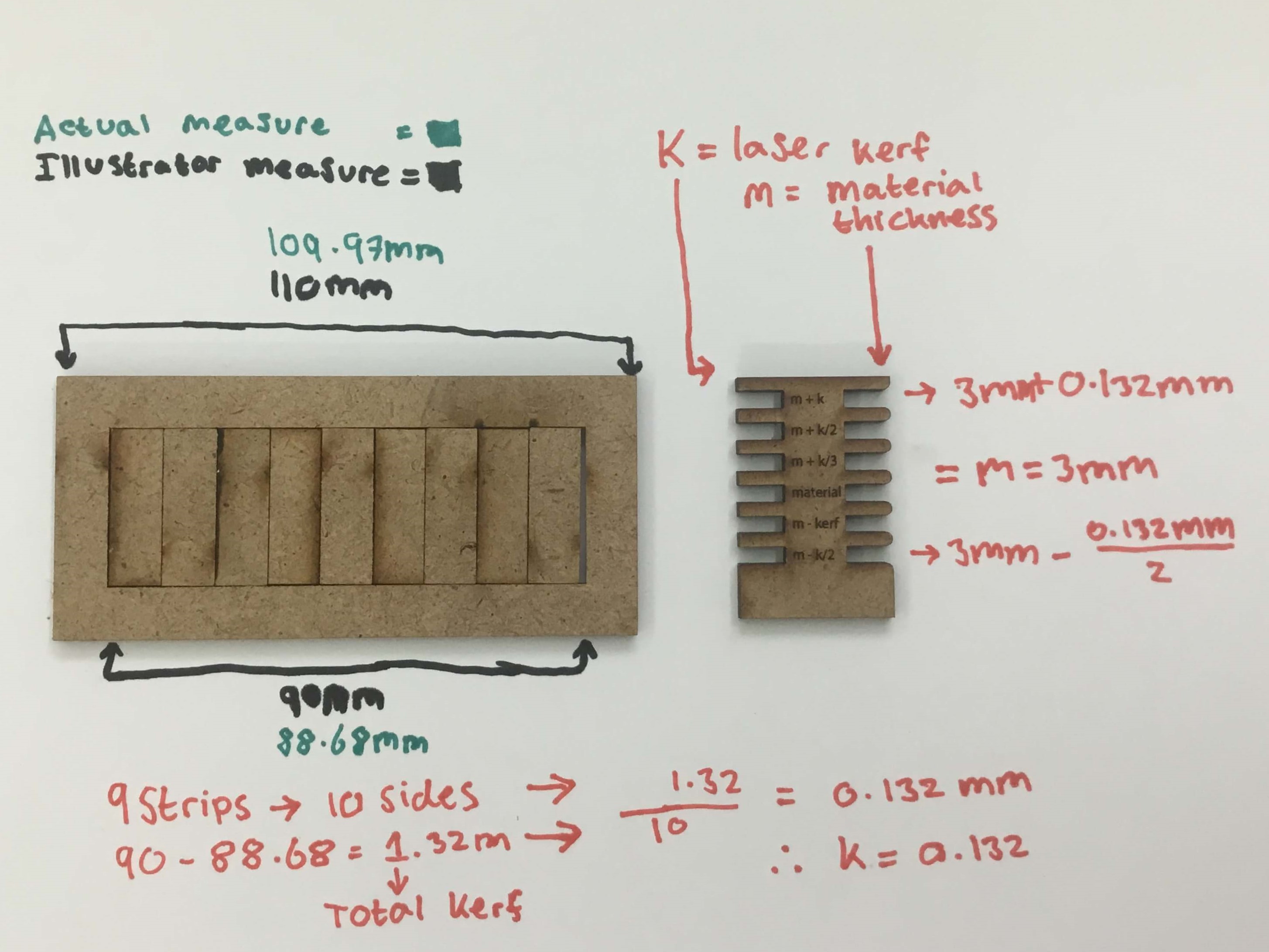
I then measured them and created a graphic to explain the kerf.
- Bars
- Frame
- Measuring Bars
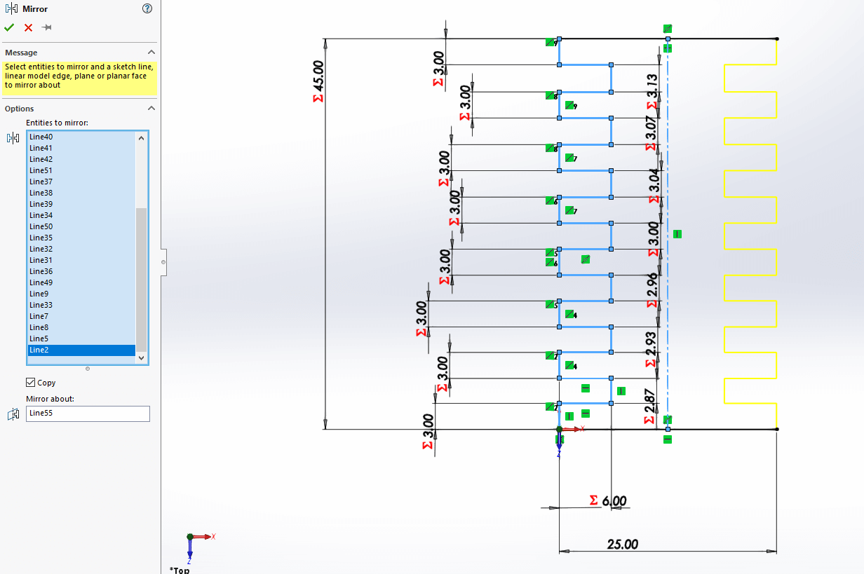
Solidworks
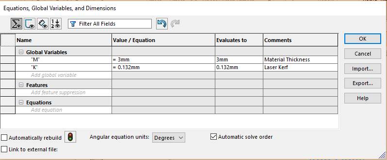
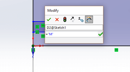
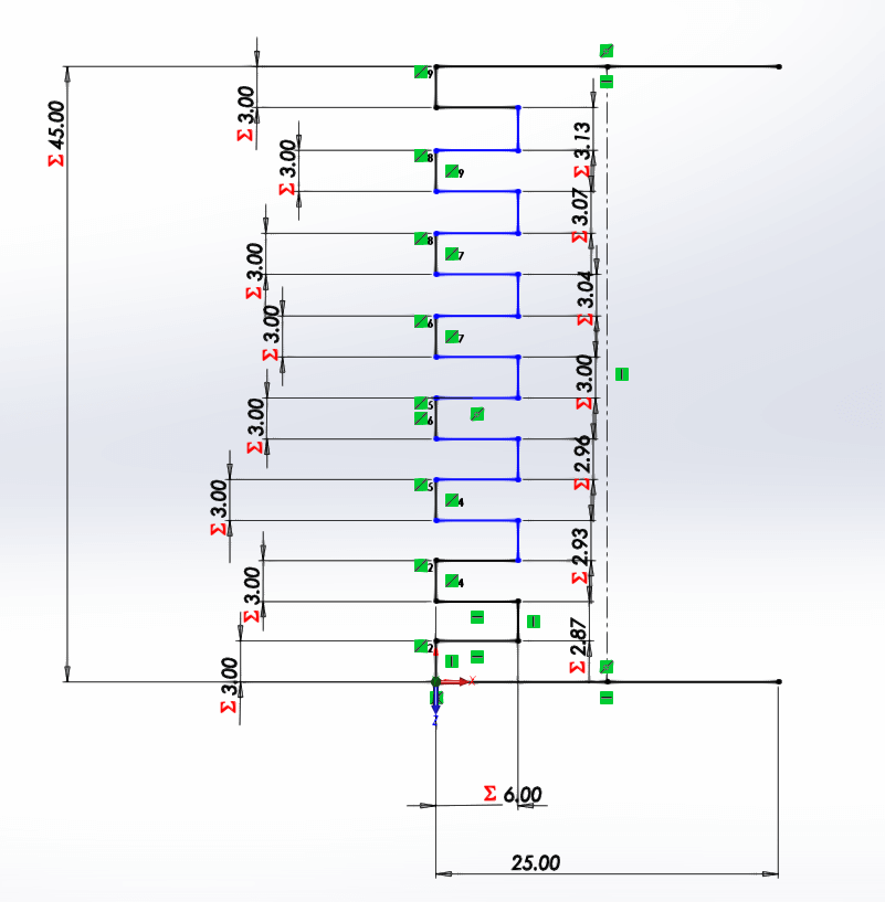
I decided to model this comb, based on equations and parameters. This requried setting up variables in the equations menu.
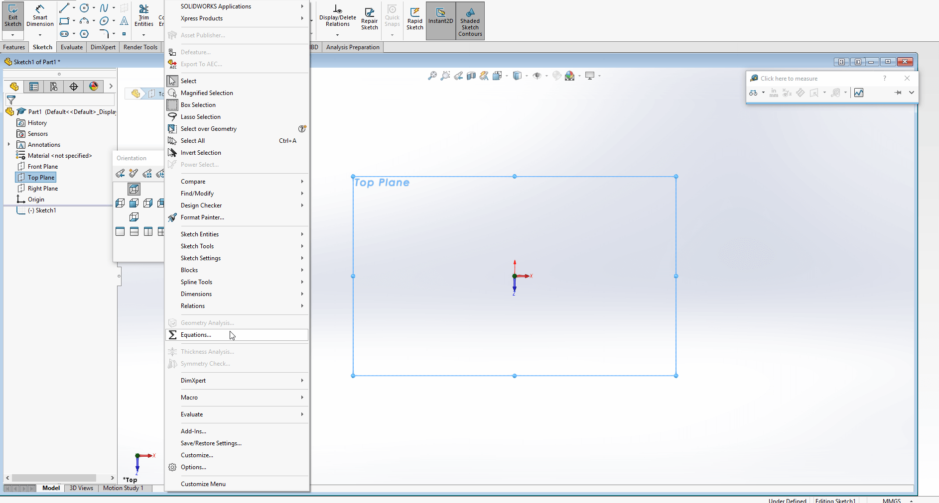
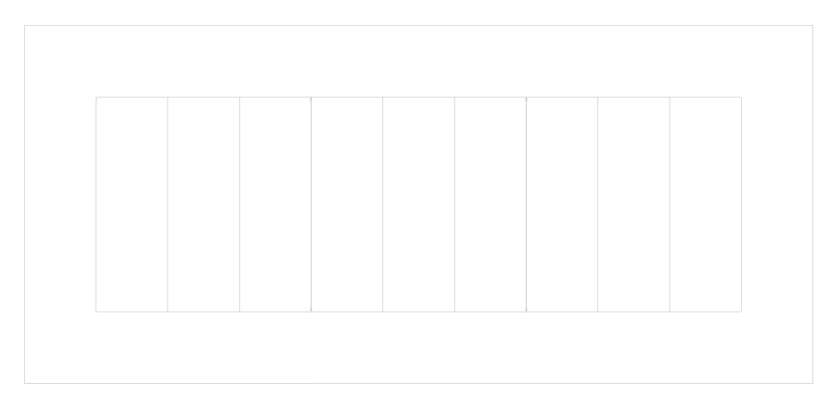
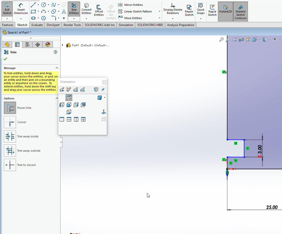
I then drew a square:
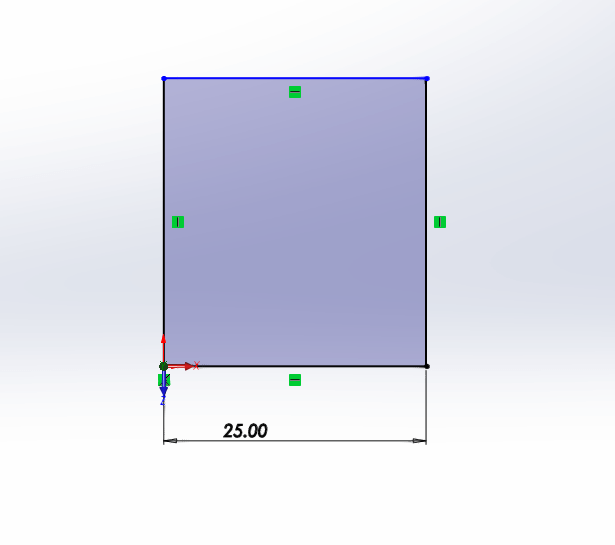
Adding and parametrically setting the dimensions
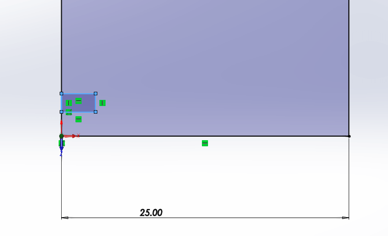
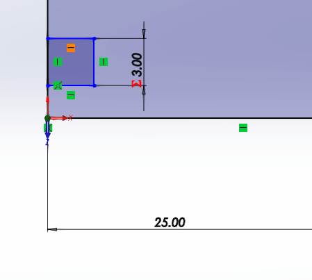
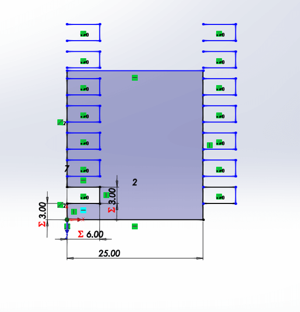
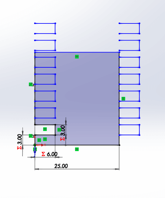
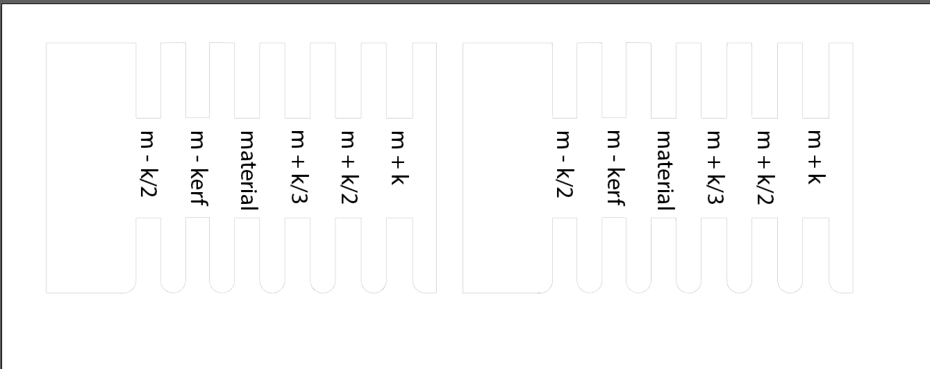
There are a lot of equations at play, but it's material in the middle with /2 or /3 of the kerf thickness added or subtracted out either side.
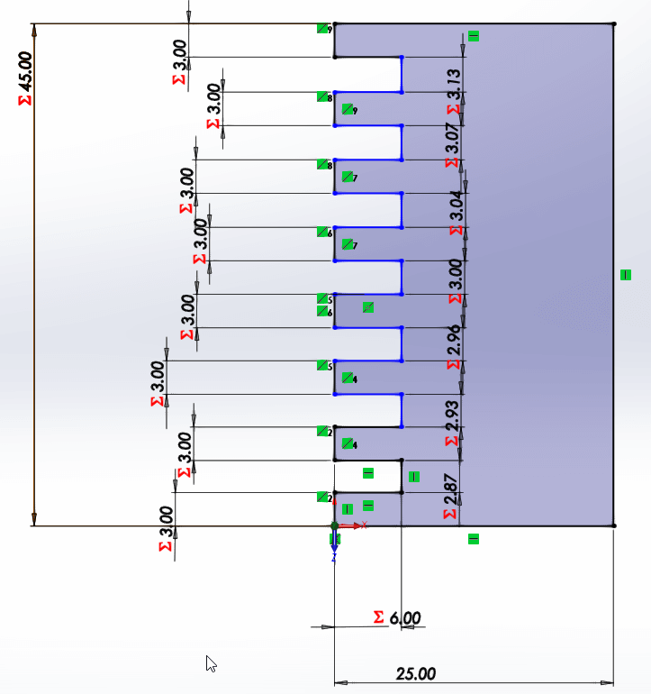
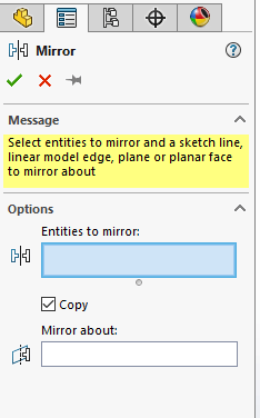
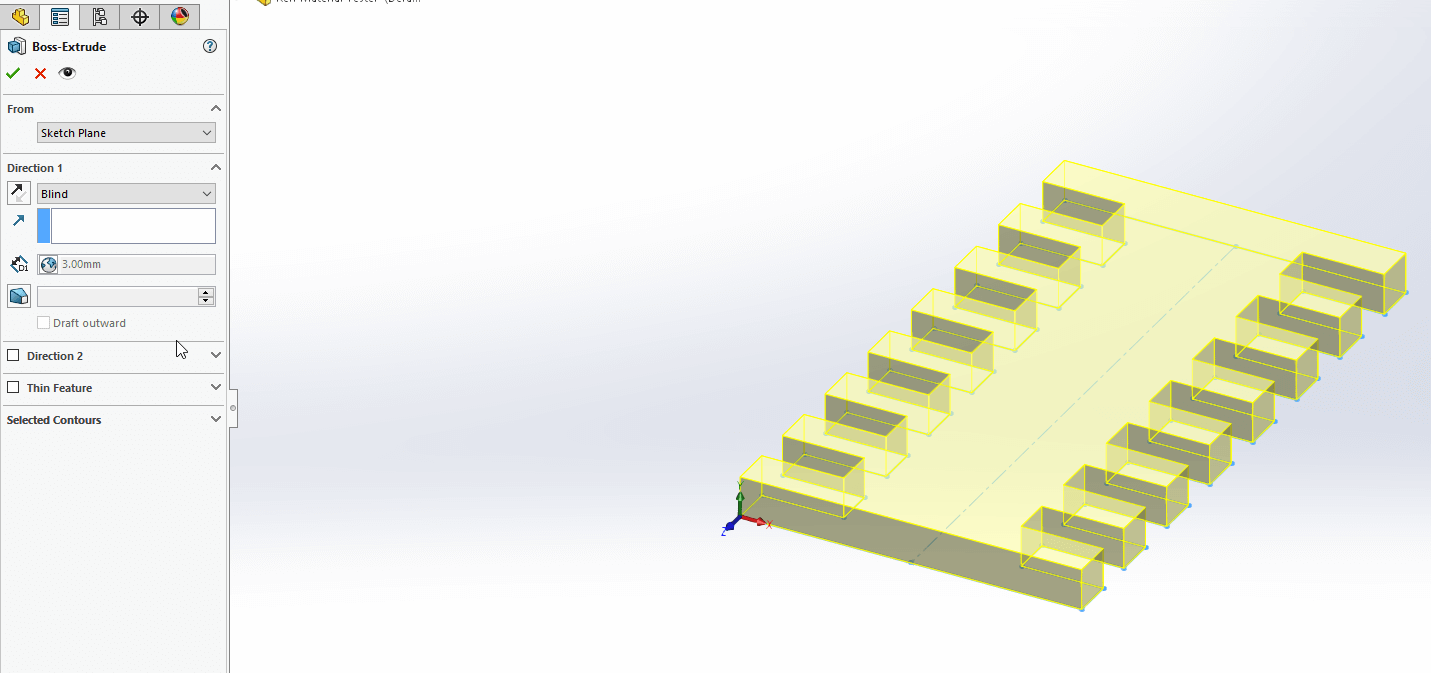
I mirrored the comb to the other side to complete the part:
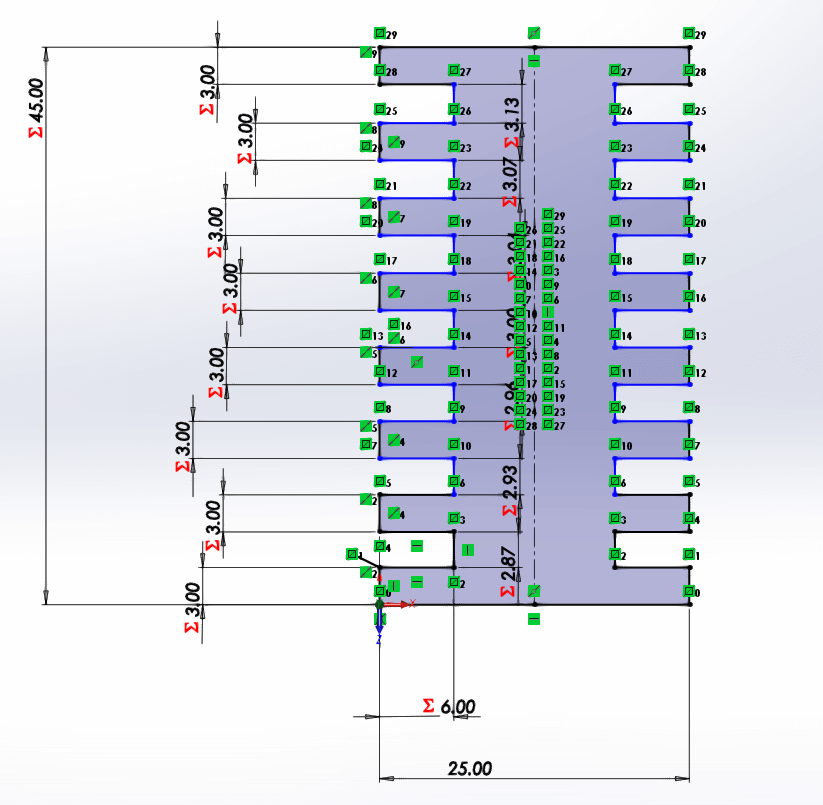
The extrusion is based on the material thickness variable as well, when the material is changed the whole thing will change.
However due to the nature of the part that I set up it is only going to work for a section of material thicknesses, because the part width is set at 25mm/1inch rather than based on the parameter of the thickness.
There always seems to be more than I can think about at one time, but I am learning, slowly.